Eight nodes, one insulated box of air. Each node heats the shared bath under load and reads only its own sensor. Goal: ambient settles to setpoint with nobody in charge.
| Qty | Item | Notes |
|---|---|---|
| 8 | ESP32-S3 N16R8 (ESP32-S3-DevKitC-1 layout) | Lonely Binary / any DevKitC-1-layout S3; internal temp sensor works in a pinch |
| 8 | DS18B20 temperature sensors | or NTC + ADC divider; one per node, local only |
| 8 | 4.7 kΩ pull-up resistors | DS18B20 data line |
| 8 | power resistors ~10 Ω / 5 W (optional) | heat source; CPU busy-loop is the free alternative |
| 1 | insulated enclosure | cooler, foam box, or capped pipe length |
| — | USB power for all boards | a powered hub or two; cables exit through one notch |
| Signal | ESP32 pin | Connects to |
|---|---|---|
| DS18B20 data | GPIO 4 | sensor data, 4.7 kΩ pull-up to 3V3 |
| DS18B20 VDD / GND | 3V3 / GND | sensor power |
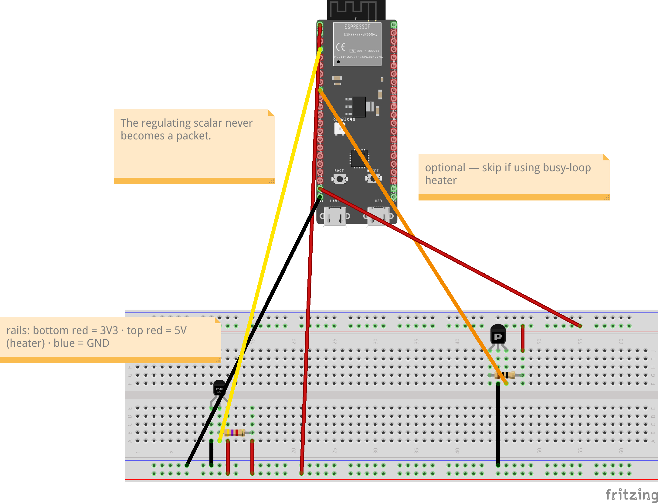
| Load PWM | GPIO 16 | gate of small MOSFET switching the 10 Ω resistor across 5 V (skip entirely if using the busy-loop as the heater) |
Board (ESP32-S3-DevKitC-1 layout, N16R8): GPIO 4 and GPIO 16 exist on the S3 and are unchanged from the classic-ESP32 wiring (1-Wire is pin-agnostic; GPIO 16 is a legal LEDC/PWM pin). On octal-PSRAM N16R8 leave GPIO 33–37 (PSRAM) and GPIO 26–32 (SPI flash) alone — touching them crashes the cache; safe GPIOs are 1–18, 21, 38–42, 47.
Nothing is wired between boards for control. The only shared thing is the air. Mount sensors in free air near each board, not touching the heater resistor.
Per-node wiring, breadboard view — heater block at right is the optional section; MOSFET drawn by pin name (D·S·G), check your package's datasheet before wiring. Pin positions are correct; the USB connector shown is cosmetic (micro-USB in the drawing vs the lab boards' dual USB-C). Editable sketch: lab1_thermal_wiring.fzz
Screw terminals, not breadboards. The wiring diagram above shows a breadboard because that is what Fritzing draws; the reference build does not use one. Each ESP32-S3 is seated in a screw-terminal breakout base, and each sensor is a small soldered assembly — a pigtail — that screws into three terminals. Nine breadboards would be nine more things to knock loose in a box you open, poke, and reseal repeatedly. The wiring is identical either way — DS18B20 data to GPIO 4, a 4.7 kΩ pull-up between data and 3V3, power and ground to 3V3 and GND — only the mechanical mounting differs. Building on breadboards? Follow the diagram literally and keep the sensor on leads.
Build a pigtail — nine of them (eight nodes and the gauge), roughly an hour sitting down. Per assembly: one DS18B20 (TO-92), three wires 10–15 cm long, three short lengths of heatshrink for the legs, one larger piece to sleeve the bundle.
Before you seal the box: measure the spread. The sub-dollar sensors are not laboratory instruments and do not agree with each other perfectly. Before mounting them, pile all nine in one spot, let them sit ten minutes, and log them together; record how far apart they read and publish that number alongside your results — a stated uncertainty makes a result credible, an unstated one makes it suspicious.
Do not correct the node sensors. Nine nodes with slightly different ideas of the setpoint is not contamination of the experiment — it is the experiment: heterogeneous participants sharing one medium, regulating anyway. Correcting them would also require per-node configuration, and every node running byte-identical firmware is the point. Correct the gauge if you like — it is an instrument, not a participant, and its correction happens on the logging machine.
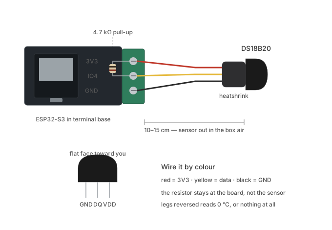
Sensor on a soldered pigtail into the terminal base: the 4.7 kΩ pull-up bridges 3V3 and IO4 at the board, and the TO-92 sits 10–15 cm out in the box air. Inset shows the TO-92 pin order, flat face toward you.
SETPOINT = 30.0        # °C, the collective target
GAIN     = 0.15        # droop slope — how hard to back off per degree over

every 2 s:
    t = read_own_DS18B20()
    duty = clamp(1.0 - GAIN * (t - SETPOINT), 0.0, 1.0)
    set_load_pwm(duty)          # or: busy-loop for duty fraction of the window
    # tell no one. write nothing to the network.
One extra sensor in the box center on a WIRED serial line out to a laptop — not on any node, not on WiFi it doesn't need. Log timestamp + °C. The gauge observes the bath; it is never in the control path. (Telemetry radio here would only add a small constant heat term, but wired keeps the demo pure.)
Keep every gauge log. Disturbance → recovery → nobody in charge is the thesis in one plot.