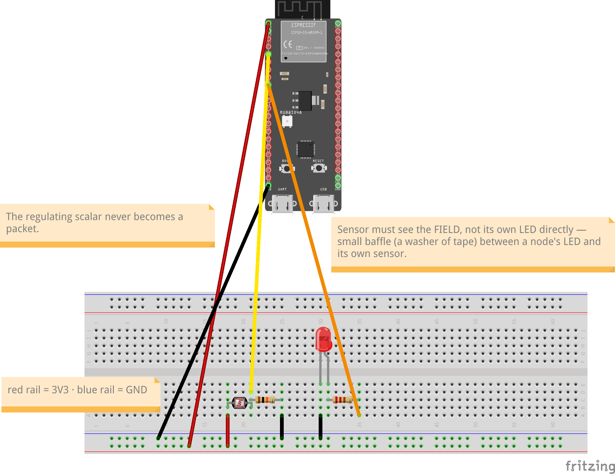
Eight nodes in one space. Each emits light into the shared field and senses the total field at its own spot, dimming where it's bright. A spatial gradient emerges — diffusion you can see and map. (Light variant; the RSSI variant exists but the light version is the visible, clean one.)
| Qty | Item | Notes |
|---|---|---|
| 8 | ESP32-S3 N16R8 (ESP32-S3-DevKitC-1 layout) | Lonely Binary / any DevKitC-1-layout S3 |
| 8 | photodiodes or LDRs | LDR + 10 kΩ divider is the cheap path; face UP into the field |
| 8 | diffuse white LEDs + ~220 Ω resistors | emitters; diffuse beats clear (spreads into the bath) |
| 1 | shared enclosure | closed box with light walls, or a dim room; ambient light is a confounder — control it |
| — | USB power for all boards |
| Signal | ESP32 pin | Connects to |
|---|---|---|
| Field sense | GPIO 5 (ADC1) | LDR/photodiode divider midpoint (LDR to 3V3, 10 kΩ to GND) |
| LED PWM | GPIO 16 | 220 Ω → LED → GND; LED aimed up/out into shared space |
Board (ESP32-S3-DevKitC-1 layout, N16R8): sense is GPIO 5 (S3 ADC1 = GPIO 1–10, WiFi-safe); the classic-ESP32 GPIO 34 is not an ADC pin on the S3. On octal-PSRAM N16R8 leave GPIO 33–37 (PSRAM) and GPIO 26–32 (SPI flash) alone — touching them crashes the cache; safe GPIOs are 1–18, 21, 38–42, 47. The onboard RGB LED (GPIO 48) is not the field emitter — use the external diffuse white LED above.
Sensor must see the FIELD, not its own LED directly — small baffle (a washer of tape) between a node's LED and its own sensor keeps self-glare from dominating the common-bath reading. Spacing matters: spread the 8 nodes so gradients have room.
Per-node wiring, breadboard view — LED drawn red by the stock part; use a diffuse white LED on the bench. Pin positions are correct; the USB connector shown is cosmetic (micro-USB in the drawing vs the lab boards' dual USB-C). Editable sketch: lab3_field_wiring.fzz
F_SET = calibrated mid-scale reading    # the collective field target
GAIN  = tune on the bench (start 0.002 per ADC count)

every 100 ms:
    f = read_field_adc()
    duty = clamp(1.0 - GAIN * (f - F_SET), 0.0, 1.0)
    set_led_pwm(duty)
    # bright neighborhood → this node dims. no messages. ever.
One roaming sensor (phone lux meter, or a spare ESP32 + LDR on a WIRED serial lead) sampled at marked grid positions maps the spatial gradient. WiFi telemetry is acceptable in the light variant per the corollary — but the wired lead costs nothing and keeps the demo unarguable.